The Allstar software, commonly called ASL3, is a version of Asterisk that has been written for the ease of use. It is extremely similar in a lot of ways to HAMVOIP, however, there are subtle differences that have made each gain their own fans independently. There are so many radio and interface options that it is not possible to write a tutorial for every situation, however the basics remain the same. You must have a cable for your radio and an interface that plugs into your Raspberry Pi via USB. If you want information regarding the interfaces we have used, please see the page on interfaces here.
I feel that most times HAM radio hobbyists don’t always entirely understand the differences, and the advantages that each can bring, but they get used to certain setups and stick with them after having been successful multiple times with their favorite ‘flavor’ of Asterisk.
Firstly, Asterisk is the ‘home’ software that is used for what has become known as the Allstar network and it was written as a VOIP telephone switching software prior to other forms of VOIP taking root in the telephone industry. The author of Asterisk maintained for many years a version that he put out for use as what we now know to be Allstar. This setup guide is for ASL3, and there is a separate write up which is very similar to this one for HAMVOIP. Just know that I prefer ASL3 for a reason, and that reason is my own, based in the statement I made earlier. I like the more modernized tools it comes with, and the more modernized (already written) functions it comes with, which makes it feel more complete to me. I am in no way an expert as to how the software is written, but I can tell you that the software writing experience I do have makes me appreciate the efforts of the authors that have made using ASL3 as easy as they have. With that said:
The first step one must take in building an Allstar node is to procure a Raspberry Pi model of choice, but I prefer the faster versions simply for their computing power. I have one node built on a Raspberry Pi4, and have built several on Raspberry Pi 5 versions. The next step is to procure a microSD card that is fast enough to keep up, and for that I choose the V30 or better rated microSD cards, at least 32Gb in size. You could use a smaller card, but the ability to have plenty of storage should you choose to expand on the functions is nice so you don’t have to upgrade it later. The very next steps come with screenshots or photos attached:
In order to burn the ASL3 image onto the microSD card, you will need to download the Raspberry Pi Imager from here (all links will open a new tab). Download the appropriate version, whether it is for Windows, macOS, or Linux, and then install it according to instructions given on the Raspberry Pi website. Once installed, you should be able to run the software and obtain a screen similar to the following: (Note: The microSD card should be plugged into your computer with its adapter prior to beginning.)
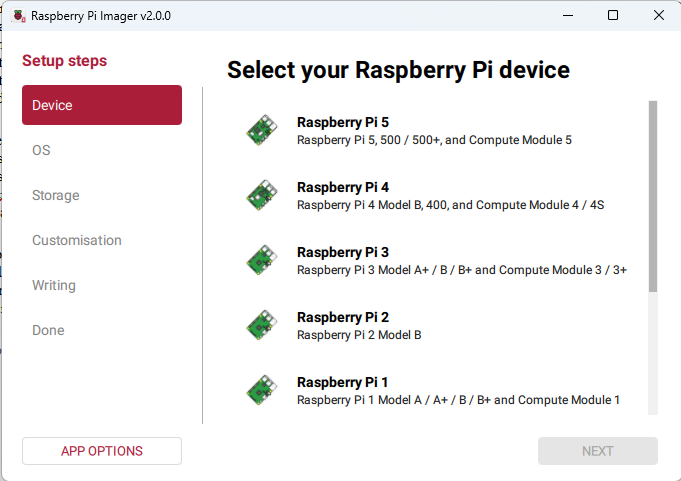
Choose the device that you are going to be using, in my case it would be a Raspberry Pi 4, by clicking on the device list, and then click ‘Next’. This will bring up a screen that looks like:
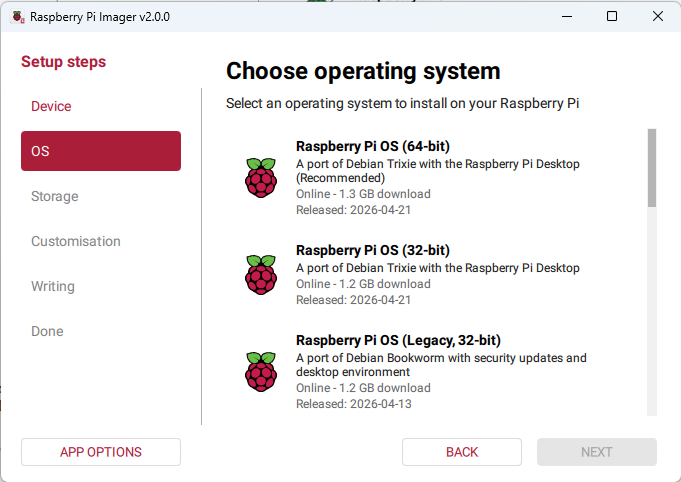
Click on the ‘App Options’ button to the bottom left. This will bring up a screen that looks like:
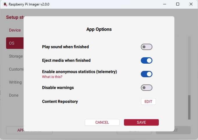
Click on the ‘Edit’ button and then click on the ‘Use custom URL’ radio button , then copy and paste into it https://rpi.allstarlink.org/latest.json
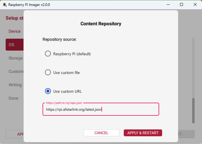
Click the ‘Apply & Restart’ button. Then re-select the device you’re programming for, again, in my case Raspberry Pi 4.
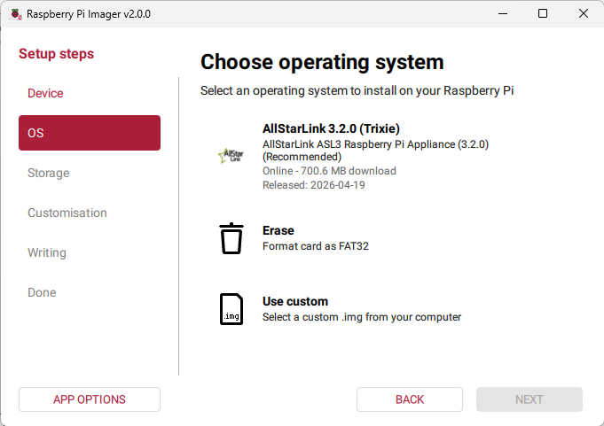
Select the AllStarLink version that is listed, and then click the ‘Next’ button.
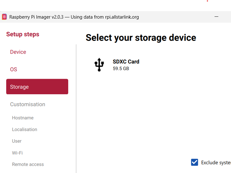
Select your storage media (the microSD card you didn’t forget to plug in before you started) and then click the ‘Next’ button again.
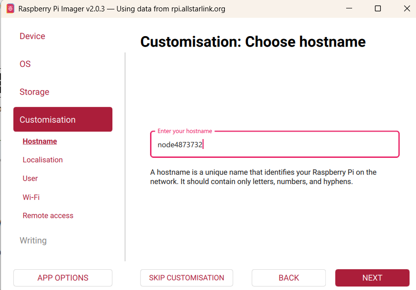
The customization portion should not be skipped, and should be stepped through. In my case, I’m using node number 4873732. Here I type in node4873732 as the hostname so that when I type into a browser address bar node4873732.local, the browser will load the node dashboard and allow me to either enter the Admin Portal or the Link Portal to control the node. We’re almost there.
Once you’ve entered the above, click ‘Next” and you will be lead to the Localization screen where you choose the timezone you’re in, and the keyboard settings. I choose Washington DC as the capital, America/New_York as the timezone, and US for the keyboard layout. Clicking ‘Next’ then brings you to the User input. Input your username to log in to the dashboard and your chosen password. Clicking ‘Next’ then brings you to the Wi-Fi setup, which in my case isn’t used because I hard wire using LAN, however, if you wish to use Wi-Fi, enter that information on this screen. Clicking ‘Next’ then takes you to the Remote access screen, I use SSL, so I check that, and then make sure it is set to password, and then click ‘Next’ again and it will prompt you to wait for a few seconds until a ‘Write’ button appears. Clicking that will introduce you to a few moments where you can then go and retrieve a nice beverage. Once the Verification step is completed, you can remove the microSD card from the computer and then put into your Raspberry Pi.
The first boot of the Raspberry Pi will take around 90 seconds or so. Once it is completely booted you can open a browser and type your “nodeYourNodeNumber.local’ into the address bar and hit enter. In my case it’s node4873732.local. The following images may not align with that number, but don’t get caught up in that for now.) Assuming you’ve done everything correctly, at this point you should see a screen that looks similar to the following.
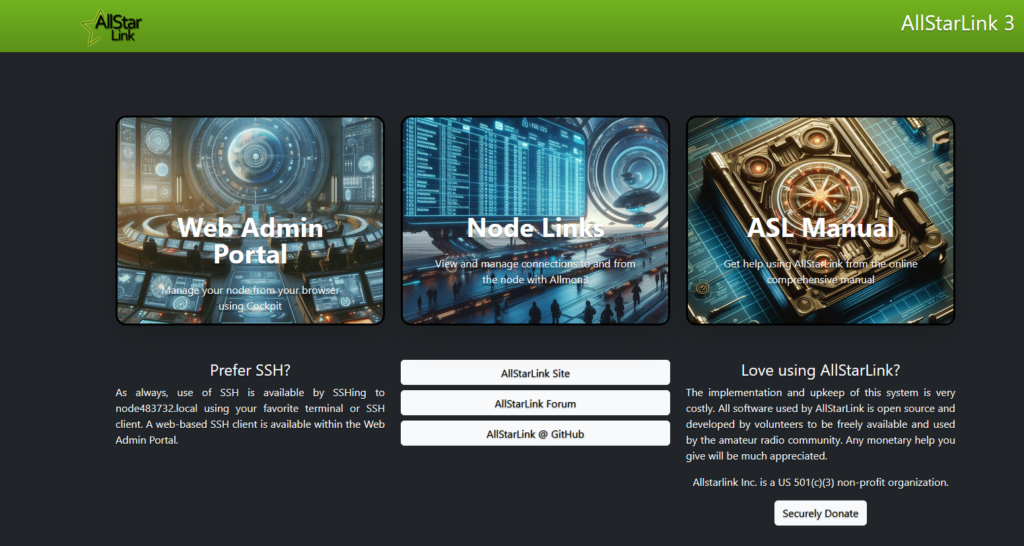
Clicking on Web Admin Portal brings you to the login screen.
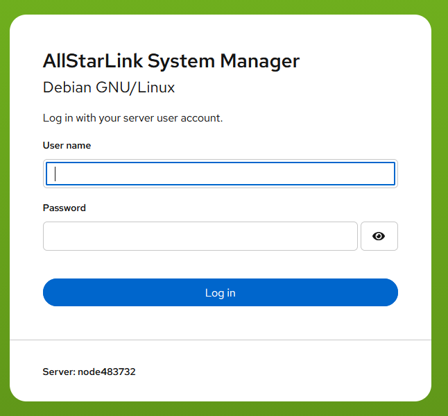
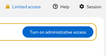
Entering the information you entered during the Raspberry Pi Imaging steps, you will be logged in to the dashboard where you will see button that looks like the following. Click on ‘Turn on administrative access’ to allow administration of the node. (It is good practice to turn this feature off when you have completed any tasks that required its use so that the node is secure.)
Once administrative access is active, scroll down until you see the Software Update menu item on the left menu. It is good practice to update the ASL3 software prior to making any changes on a fresh install. While the install software is typically the most current version, there are times when they have pushed updates but haven’t replaced the install software with the updated version yet, and this step ensures that you are updated to the latest version, which is the most secure.
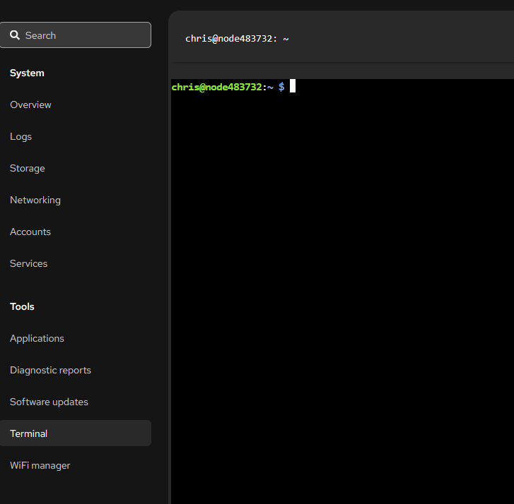
Once you’ve updated the software, click on the Terminal menu item on the left menu. It will change the screen to the following.
Type in ‘sudo asl-menu’ and hit enter.
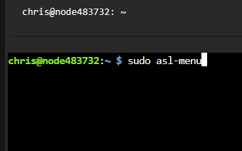
After hitting enter, the menu will open, which looks like the following.
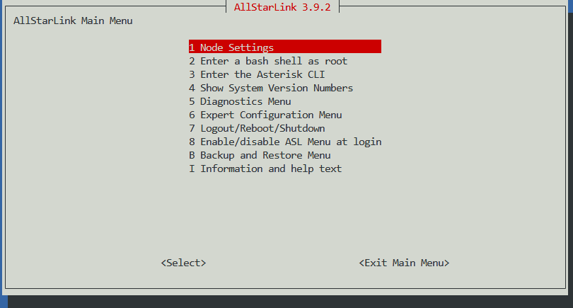
When in this menu, you will have to use the up, down, right, and left arrows on your keyboard to move the highlight to the desired menu item, tab to go from the menu item to <Select> or <Exit Main Menu>, and if there is a choice to be made, the arrows to highlight the choice and the space bar to make it active. Leave the highlight on Node Settings and hit enter.
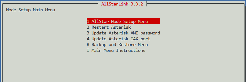
Leave the highlight on AllStar Node Setup Menu and hit enter. Following the order of the menu items, enter the node number that you obtained from AllstarLink.org. (If you haven’t done this yet, see the tutorial on how to apply for a node number here(enter the tutorial link)).
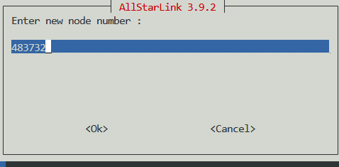
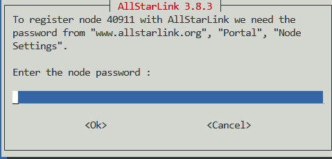
Once you’ve entered the node number for the node you’re building, you’ll need to enter the password that is assigned to the node on the Allstarlink.org site in the portal. You will have to find your node number in ‘Nodes’ and click ‘Show’ for the password to appear.
Enter the call sign that you are using for the node, typically your own unless you’re me and building a node for everyone else.
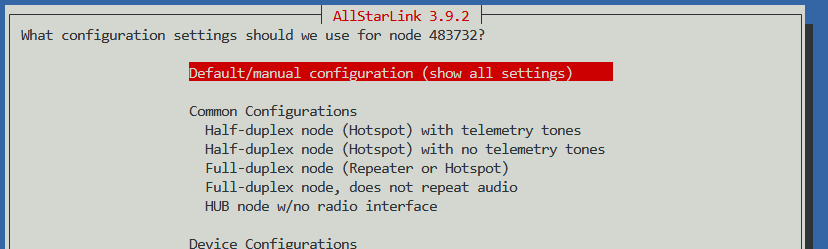
At some point, you will have gotten the screen that looks similar to the following during the node setup menu. Leave it on Default/manual configuration. You should also select SimpleUSB as the setting for radio interface. USBRadio is typically used for repeaters that need many more controls than are built into SimpleUSB.
After you’ve entered all of the information for the node setup, you’re almost there. You may need to change the IAX port if you are going to host more than one node behind a single router. In my case, I have more than one, so I have to utilize different IAX ports. The default port is 4569. I have the capability to have up to four nodes behind my router, each setup on their own ‘server’ on the allstarlink.org website as I’ve previously described. The first has an IAX port of 4569, second is 4570, and so on. In the IAX Port section of the setup menu, make sure you are changing this default port only if you plan on having more than one node operational at a time behind your router. Otherwise, only one node will connect (the first one you’ve booted) at a time and be available for connection. You will have to ‘build a server’ for each IAX port that you need on the Allstarlink.org site, under the Portal, Server Settings.
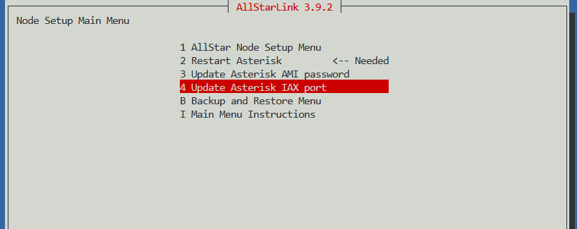
After you’ve added the IAX port, highlight Restart Asterisk and hit Tab until you are on <Select> and hit enter. This will restart your Asterisk, which will then make your node live.
On the main screen of the menu, highlight ‘Expert Configuration Menu’ and hit enter.
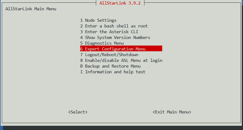
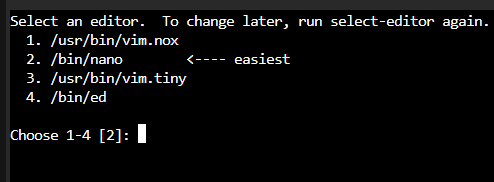
The next menu will come up with the top being rpt.conf. Highlight this and hit enter. The following will appear only once, and is asking what editor you wish to use. Type 2 and hit enter.
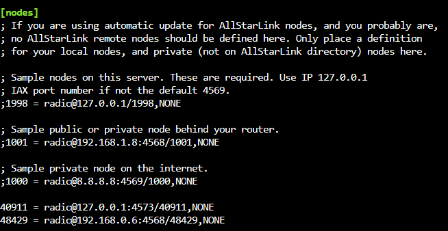
The configuration file will contain an entry under [Nodes] that is your node number you entered earlier. If you have other nodes inside your router, you must add them here (on each node’s rpt.conf file). They must be typed exactly like this picture at the bottom where you see 48429 = radio@192.168.0.6:4568/48429,NONE. In my case here, I have to open the rpt.conf file on the node 48429 and add 40911’s information on that rpt.conf.
At this point, you’re basically done setting up your node, except for the simpleUSB.conf file. We’ll head there next.
Depending upon your radio, connection to the radio, and other factors, the settings will have to be tested so the radio functions as it should. You must know if your radio is a positive or ground PTT, for instance.
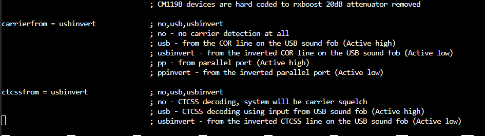
The ptt settings are typically fine with the default settings of invertptt = no for Yaesu radios.

The most important part of the SimpleUSB.conf file is the bottom lines of code, which are your tunings for the audio levels. There is a menu we’ll explore in another tutorial for setting volumes more precisely using an automated portion of the program. It’s also used for testing to see if the radio is working with your settings, and correcting them to make it work.
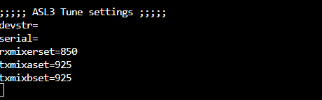
We’ve found that these numerical values are best for our system.
Now that we’ve completed (for the most part) setting up your node, we’ll move on to making Allmon 3 work more gooder, er better. First, you have to input a password and create your user or you won’t be able to log in. Let’s do that now. At the terminal of the dashboard :

At the prompt up top, type in sudo allmon3-passwrd <your name> and hit enter. It will then prompt you to enter the password you want to use, and then a second time when you hit enter.

Now you can log in to the Allmon 3 node dashboard. Go back to the main node<yournodenumber>.local

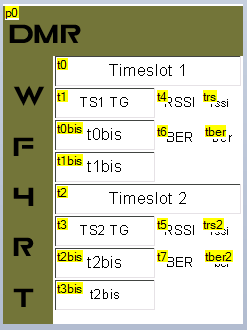
Click on Node Links and it will open your Allmon3 Monitoring Dashboard.
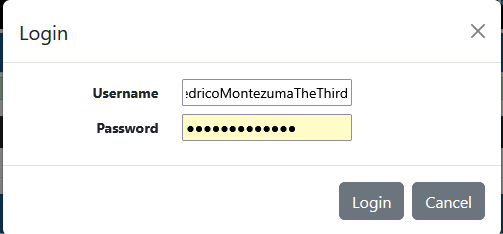
Click on the ‘Login’ button and enter your user name and the password you input on the previous step.
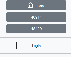
The controls that you see in the upper right corner of the dashboard are what you will use to control the node. They look like:

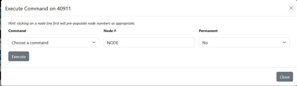
The two main buttons you will use are the gear and the link. First, click on the gear.
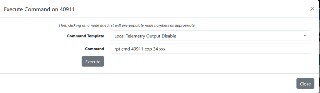
The drop down has useful commands. The most useful at the moment will be ‘Local Telemetry Output Disable’. Click it, and then click execute. You should get a green success message, which rocks.
Next, we’ll attempt to connect the node to another node. This is the fun part. Before you proceed with the connection to another node, you should make sure the radio is working with the node, and do all testing prior to connecting to another node so that you don’t disrupt the conversations that may be taking place on the system you are connecting to. Let’s assume you’ve done that. Click on the Link button on the top right.
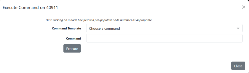
Click on the dropdown that says Choose a command and click ‘Connect’. Type in the node number you want to connect to, in this case I’ve typed 48429. If you want your node to connect automatically if the node you’re connecting to goes down temporarily, click the dropdown for Permanent and click ‘Yes’.
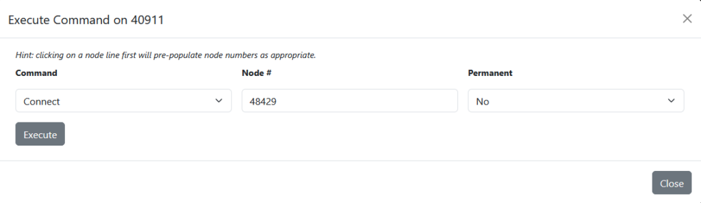
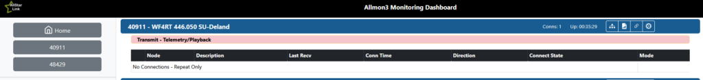
Click Execute. If your setup is working, it will connect and show similar to the following.

If the Connect State says ‘Connecting’ and doesn’t change until the connection times out, there is something wrong and you should go through your setup to make sure you’ve setup your node properly. If you need help, contact us and we’ll be happy to help!
Until next time…
~73, WF4RT
 Nextion Screen Programming for Pi-Star Stack (Moderate)
  Pi-Star Setup, Our Way
 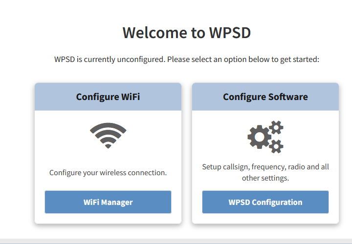 WPSD Setup, Our Way
  Meshtastic Vs. MeshCore